Premium interior roof lantern and skylight roller blinds use mains powered motors inside an aluminium headbox. These blinds use dimensionally stable roller fabrics to control heat and daylight under modern glazing. They need a clean, direct electrical feed to the upstand for safe, hidden installation.
This guide explains how to prepare electrics for mains powered roof blinds at any stage of a build. It shows you how to prevent electrical mistakes to future‑proofing your wiring.
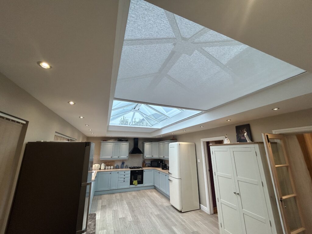
Understanding Mains Powered Roof Blind Systems
Motor Type
These blinds use mains powered motors manufactured by Somfy, Lutron or Becker
- The tubular motors sit inside the fabric tube usually within a headbox
- The motor cable length is typically 3 metres
- The motor cable is designed to be routed behind plasterboard with no visible wiring
Cable Type
Cable requirements remain consistent across most systems.
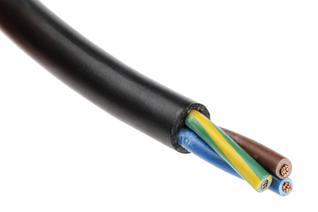
- Remote control motors and most hardwired versions use 3‑core 0.75 mm² flexible cable backed by a 5A fuse
- Hardwired automation motors may use 5‑core cable for directional control. This becomes essential when you integrate your roof lantern blind with home automation systems such as Crestron, KNX, Lutron or RAKO.
Electrical Load
Premium mains‑powered roof blind motors draw around 1.1 amps during normal operation. At start up, the current briefly increases to approximately 2.2 amps. This load is low, meaning a 5A fused connection handles it comfortably, depending on what else is on the circuit.
Why Power Must Reach the Upstand
The roof blind headbox sits on the upstand, and the motor sits inside the headbox. The power cable must appear at the upstand so it can connect cleanly to the blind’s motor. A spur on the living‑space wall outside the upstand, naturally forces chasing and redecorating. Delivering power directly to your upstand avoids disruption and ensures a professional finish.
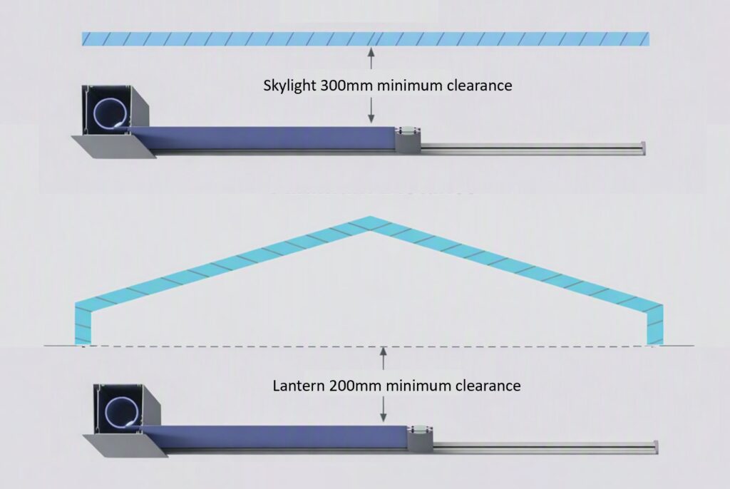
Minimum Blind Positioning Distances
As you plan the blind’s location, you must maintain safe distances from the glass to protect fabrics from heat buildup.
- 200 mm below glass for roof lanterns
- 300 mm below glass for flat skylights
These clearances determine where spurs and flex cables can sit without obstructing the headbox or side channels.
Positioning a 5A Switched Fused Spur
If you have not yet chosen the blind model, the next logical step is future‑proofing the electrics.
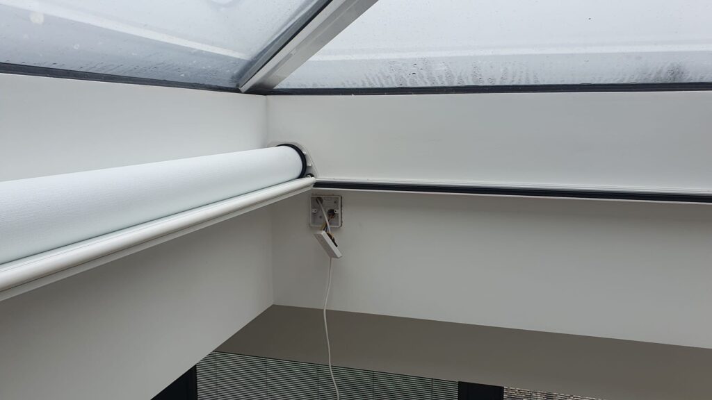
- Install a 5A switched fuse spur flush with the plasterboard on the upstand.
Spur Placement Rules
As you refine the placement, follow these rules:
- Place on the long side of the blind
- Position above or below the side channel
- Keep in front of the headbox
- Minimum 200 mm from the end of the upstand
- Largest headbox width is ~170 mm, so 200 mm avoids obstruction
- Motor cable routes behind plasterboard with no visible wiring
Using Power Flex Instead of a Spur
If you prefer the fused spur elsewhere, you can still maintain a clean installation by ensuring the flex cable appears at the upstand.
Flex Cable Positioning
As you position the flex, follow these distances:
- 50 mm from the end of the upstand
- Hidden behind the headbox
- Must align with final blind height
- 200 mm below top of upstand for lanterns
- 300 mm below top of upstand for skylights
Cable Entry Position for Blindspace Concealed Roof Blinds
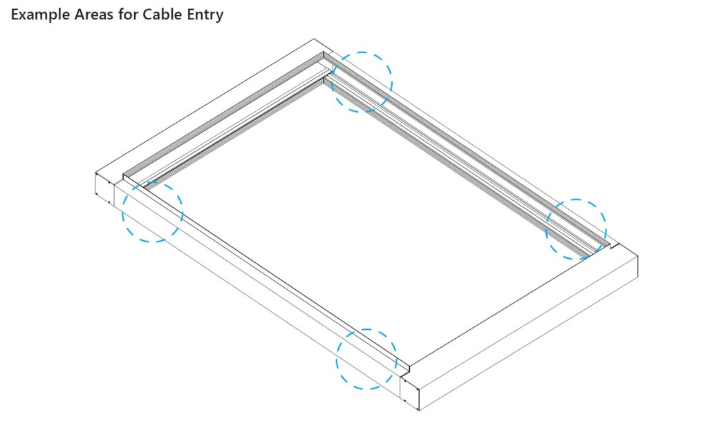
When Blindspace concealment boxes are being used during the build to conceal the blinds hardware, the cable must enter through the Blindspace side‑channel boxing. The cable entry is approximately 350 mm from the end of the upstand and still needs to be backed by a 5A fuse.
The flex cable enters the blind through a 20 mm hole in the side channel and a cable grommet should be used to protect the cable
- Entry point sits 120 mm down from the top of the side channel
- Hole positioned 40 mm from either the top or bottom edge, depending on whether the blind’s side channels are top‑supported or bottom‑supported
- In most installations, the entry point is positioned at the bottom
This placement ensures the cable feeds directly towards the headbox area without interfering with the blind mechanism, maintaining a clean architectural finish. This article gives you more detailed information on Blindspace Electric Roof Blinds Designing Roof Lanterns & Skylights for Blindspace. The Complete Guide to Concealing Athena Electric Roof Blinds. – WindowTreat
Summary: Power Feed for Roof Blinds
All mains powered roof lantern and skylight blinds need the electrical supply to terminate in the upstand. This is essential for a clean and hidden connection directly into the blind motor inside the headbox. Bringing power to the wall or ceiling causes visible cables and future rework.
Once power reaches the upstand, the final position depends on the minimum fabric clearances and the chosen power method. These options include a 5A spur, a fuse backed flex cable, or a Blindspace concealment system.
| Method | Positioning Guidance | Notes |
|---|---|---|
| 5A switched spur | Flush with plasterboard on the upstand. Place 200 mm from the end of the upstand. Keep above or below the side channel and in front of the headbox. | Avoids obstruction. Motor cable routes behind plasterboard with no visible wiring. |
| Fuse backed flex cable | Bring the flex out of the upstand 50 mm from the end. Hide behind the headbox. Align with blind height. Use 200 mm below glass for lanterns and 300 mm for skylights. | Clean installation when the spur is located elsewhere. |
| Blindspace concealment | Cable enters through the Blindspace side channel boxing. Entry point is 350 mm from the end of the upstand. Use a 20 mm hole with a grommet. Position 120 mm down from the top of the side channel. | Ensures the cable feeds directly toward the headbox without interfering with the blind mechanism. |
Supporting Links
Most Roof Lantern Blinds Sag. Here’s Why.
How Claire Transformed Her Orangery with Hercules – WindowTreat